Showing posts with label Regulator. Show all posts

Sunday, November 10, 2013

Rectifier Circuit - diode and Reservoir capacitor (Smoothing Capacitor)

Rectifier and  Reservoir capacitor

The rectifier is circuit that convert AC voltage to DC voltage. The diode (D1) is the component playing at main roll. In rectifier, there always have capacitor (C1) as filter, to reduce the output voltage ripple.
The C1 called as Reservoir capacitor (Smoothing Capacitor).
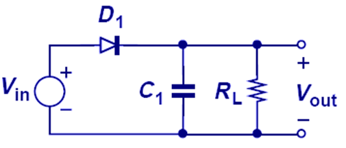
Below is the input voltage and output voltage for the circuit. The output contain some voltage ripple, where the voltage ripple can reduce by increase the C1 capacitance.


When C1 value is increasing, the source need supply more current to charge the C1, where that big amount of current will flow across diode (D1), cause D1 heat up.
Simulation at below shown the effect of C1 value.

The 10uf capacitor have low voltage ripple compare to 1uf, but,the I(D2) also increasing. The current is instantly increase (like pulse) with very high amplitude, it may causing the diode overload.
What is optimize value for C1 to provide the lowest voltage ripple and prevent diode over heat.

The analysis will start from capacitor (C1).
Step 1
Formula 1: (draft calculation)

Base on the circuit, the current flow from source and current flow to load is equal.
i  = I input = I diode = I load = I charge capacitor = I discharge from capacitor (in DC form)
C = capacitance
dV = The delta voltage, in this case, the voltage ripple is the level use to calculate.
dt = the charging capacitor time.
       half wave rectifier = 1/(input signal frequency)
       full wave rectifier = 1/(input signal frequency x 2)

Assuming, the design target parameter
max output current to load = 150mA
Vpeak = (Vrms x 1.414) = Vac meter measure x 1.414 = 21.21V x 1.414 = 30Vpeak
Rload = 21V/150mA = 140ohm
dV = 10% of ripple voltage = 30 x 10% = 3V
The AC signal frequency = 50Hz, haft wave rectifier.
dt = 1/50 = 0.02s

Cmin = (150mA x 0.02s) / 3V
         = 1000uf

Formula 2: (accurate calculation)
C = minimum capacitance
Vp = Vpeak
f = signal frequency
[note]   f = half wave rectifier
           2f = full wave rectifier
R = Load resistance
Vr = Vripple
result :- 
Cmin = 1428uf

The other formula for calculate the voltage ripple, but it only able apply to ripple voltage not exceed 10%

Step 2
Calculate the maximum diode current. There have 2 maximum diode current need to know.
The power supply start-up maximum current and maximum operating current.

In power supply start-up stage, the reservoir capacitor (C1) is in full discharge stage.
We may turn on the transient voltage on Vpeak, there will huge current flow throw diode to charge the capacitor, we cannot very clearly using the formula to calculate inrush current into diode, but, we can limit the current.

The Rinrush (R1) connect at before capacitor and output of rectifier circuit. It limit the maximum current flow across the diode.
Vp(on) = Vpeak. the circuit may turn on at voltage peak level.
Vdiode = voltage drop on diode (forward voltage of diode)
IFSM = the diode non-repetitive peak forward current.
             the maximum inrush current limit that affordable by diode.


Please take note that, the output current DC is not equal to the peak current flow across diode.
When charging capacitor (C1) there will have pulse current flow through the D1, that is maximum operating current.

Diode conduction time:-
Vr = Vripple
Vp = Vpeak
T = 1/frequency
dt = the diode conduction time, where the pulse current appear.
2 = half wave rectifier
4 = full wave rectifier

dt = ((1/50) / (2 x 3.142)) x ((2 x 3) / 30) ^ 0.5
    = 1.4233ms

maximum operating current:-
Ipeak = (T x Idc ) / dt
T = 1/frequency
dt = diode conduction time
Idc = average load current
Ipeak = peak current through the rectifier

Ipeak = (1/50 x 150mA) / 1.4233ms
          = 2.108A

or

design safety = 1.4 x 2.108 = 3A

For design safety, the diode IFRM (repetitive peak forward current) must around 3A.

reference:
http://proton.ucting.udg.mx/materias/CIE-24/Unidad.02/cktosDiodos.pdf
http://whites.sdsmt.edu/classes/ee320/notes/320Lecture8.pdf
http://electrapk.com/surge-current-in-capacitor-input-filter/
http://waynestegall.com/audio/ripple.htm
http://www.zen22142.zen.co.uk/Design/dcpsu.htm

Saturday, November 10, 2012

Understand Diode, LED and Diode Zener - Basic


Diode

Diode

Diode is semiconductor device that allow current flow single direction only (From Anode to Cathode). We can found difference type of diode in market, it design for difference application.

Diode type and Application
Diode - commonly used in rectifier circuit
Schottky diode - switching power supply, switching circuit, as switch in battery charger circuit.
LED (Light Emitting Diode) - indicator
photodiode - sensor
SCR (Silicon Controlled Rectifier) - power control circuit, use as switch
Pin Diode - RF circuit as RF switch
TVS (Transient Voltage Suppression) - circuit protection
Tunnel Diode - microwave circuit
Varicap - use it as voltage control variable capacitor, VCO (Voltage Control Oscillator)
Zener diode - Voltage regulator

Understand diode forward bias and reverse bias
diode forward bias
diode reverse bias
Diode Forward Bias
Diode Reverse Bias

Understand diode rating
This post only focus on normal diode rating, table at below is specification for diode 1N400x series.
1N4007 ratings from datasheet
Table from datasheet

Important parameter for diode
Breakdown Voltage (Vr, Vrrm, Vrwm) - the diode can withstand maximum voltage in reverse mode. If reverse voltage is higher than rating value, the diode may damage.
RMS Reverse Voltage (Vr(rms)) - the diode maximum DC reverse voltage. (continues reverse voltage)
Forward Voltage (Vf, Vfm) - the voltage drop across diode in forward mode. The voltage can measure by multimeter.
Non repetitive peak forward surge current (Ifsm) - maximum forward pulse current (Surge Current).
Forward Current (If, Ifm) - the diode maximum DC forward current. (continues forward current).
Peak Reverse Current (Irm) -the diode maximum leakage current in reverse mode. when diode in reverse mode, there may have some leakage current from cathode to anode.

Example:-
Base on circuit on top, the transformer step down the voltage to 52V, the 1N4001 will no applicable use in this circuit, because its Vrrm is 50V only. The 1N4002 until 1N4007 suitable for this circuit.
For datasheet, we know that, 1N400x series diode forward current is 1A. Formula at below use to find the lowest R that can support by circuit:-

Voltage divider Formula
Vin = Vfm + (Ifm x R)
52V = 1V + (1A x R)
R = (52V - 1V) / 1A
   = 51 ohm.
The R value cannot lower than 51ohm, if R lower than 51ohm, the diode may damage.

LED (Light Emitting Diode)
LED

The LED characteristics not much difference in electronic circuit. normally, the LED have higher forward voltage compare to diode. The diode forward voltage we can measure using multimeter.
Example:-
Choose resistor for LED.
Base on the circuit on top, the capacitor and series of resistor are connect parallel with LED.
We can ignore the capacitor path and series of resistor path, because parallel connection will have same voltage level.
Just assume, the input voltage is 5V, diode forward voltage = 2.2V Find the suitable R value.

Rule of thumb
The LED forward current is around 5mA to 10mA.
The forward current is parameter that control LED brightness.

Voltage divider Formula
Vinput = Vled + (If x R)
5V = 2.2V + (5mA x R)
R = (5V - 2.2V) / 5mA
R = 560 ohm

Find R power:-
P = VI
   = I²R
   = (5mA)² x 560
   = 0.014W

can use any resistor more then 0.014W.

Diode Zener
The diode zener package it look like normal diode. It forward voltage is around 0.7V (it close to normal diode), but it have difference reverse voltage value compare to normal diode.
Diode zener reverse voltage is low compare to normal diode.

Example 1
Input voltage =10V
diode zener voltage = 5.1V
Vref current = 10mA (target)
Find the R value, R power, diode zener power
1. The diode zener can regulate the voltage only, the current is control by R.
    Just assume current flow throw diode zener is 1mA and 10mA through Vref path.
    Total 11mA will flow throw R.

     Voltage divider Formula
     Vinput = Vzener + ((Iref + Iz) x R)
    10V = 5.1V + ((1mA + 10mA) x R)
     R = (10V - 5.1V) / (11mA)
         = 445 ohm
         ≈ 430 ohm

2. R power
    Find current across R
     Voltage divider Formula
     Vinput = Vzener + ((Ir) x R) 
    10V = 5.1V + (Ir x 430)
    Ir = (10V - 5.1V) /430 ohm
        = 11.4mA

    P = Ir² x R
       = (11.4mA)² x 430 ohm
       = 0.056W

3. Just assume, Vref open circuit. all current will flow across the diode zener.
    The diode zener power will be:-
    P = VI
       = 5.1V x 11.4mA
       = 0.05814 W (min)

4. The Vref = diode zener votlage = 5.1V

Example 2
Find the Vref voltage. if input voltage is 11V.
1. The Vref = Vinput - Vzener
                   = 11V - 5.1V
                   = 5.9V

2. Power for diode zener
    Itotal = Iz = Ir + Iref
    Pz = Iz x Vz