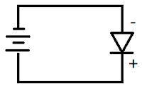
Diode
Diode is semiconductor device that allow current flow single direction only (From Anode to Cathode). We can found difference type of diode in market, it design for difference application.
Diode type and Application
Diode - commonly used in rectifier circuit
Schottky diode - switching power supply, switching circuit, as switch in battery charger circuit.
LED (Light Emitting Diode) - indicator
photodiode - sensor
SCR (Silicon Controlled Rectifier) - power control circuit, use as switch
Pin Diode - RF circuit as RF switch
TVS (Transient Voltage Suppression) - circuit protection
Tunnel Diode - microwave circuit
Varicap - use it as voltage control variable capacitor, VCO (Voltage Control Oscillator)
Zener diode - Voltage regulator
Understand diode forward bias and reverse bias
Understand diode rating
This post only focus on normal diode rating, table at below is specification for diode 1N400x series.
Important parameter for diode
Breakdown Voltage (Vr, Vrrm, Vrwm) - the diode can withstand maximum voltage in reverse mode. If reverse voltage is higher than rating value, the diode may damage.
RMS Reverse Voltage (Vr(rms)) - the diode maximum DC reverse voltage. (continues reverse voltage)
Forward Voltage (Vf, Vfm) - the voltage drop across diode in forward mode. The voltage can measure by multimeter.
Non repetitive peak forward surge current (Ifsm) - maximum forward pulse current (Surge Current).
Forward Current (If, Ifm) - the diode maximum DC forward current. (continues forward current).
Peak Reverse Current (Irm) -the diode maximum leakage current in reverse mode. when diode in reverse mode, there may have some leakage current from cathode to anode.
Example:-
For datasheet, we know that, 1N400x series diode forward current is 1A. Formula at below use to find the lowest R that can support by circuit:-
Voltage divider Formula
Vin = Vfm + (Ifm x R)
52V = 1V + (1A x R)
R = (52V - 1V) / 1A
= 51 ohm.
The R value cannot lower than 51ohm, if R lower than 51ohm, the diode may damage.
LED (Light Emitting Diode)
Example:-
Choose resistor for LED.
Base on the circuit on top, the capacitor and series of resistor are connect parallel with LED.We can ignore the capacitor path and series of resistor path, because parallel connection will have same voltage level.
Just assume, the input voltage is 5V, diode forward voltage = 2.2V Find the suitable R value.
| Rule of thumb
The LED forward current is around 5mA to 10mA. The forward current is parameter that control LED brightness. |
Voltage divider Formula
Vinput = Vled + (If x R)
5V = 2.2V + (5mA x R)
R = (5V - 2.2V) / 5mA
R = 560 ohm
Find R power:-
P = VI
= I²R
= (5mA)² x 560
= 0.014W
can use any resistor more then 0.014W.
Diode Zener
The diode zener package it look like normal diode. It forward voltage is around 0.7V (it close to normal diode), but it have difference reverse voltage value compare to normal diode.
Diode zener reverse voltage is low compare to normal diode.
Example 1
Input voltage =10V
diode zener voltage = 5.1V
Vref current = 10mA (target)
Find the R value, R power, diode zener power
1. The diode zener can regulate the voltage only, the current is control by R.
Just assume current flow throw diode zener is 1mA and 10mA through Vref path.
Total 11mA will flow throw R.
Voltage divider Formula
Vinput = Vzener + ((Iref + Iz) x R)
10V = 5.1V + ((1mA + 10mA) x R)
R = (10V - 5.1V) / (11mA)
= 445 ohm
≈ 430 ohm
2. R power
Find current across R
Voltage divider Formula
Vinput = Vzener + ((Ir) x R)
10V = 5.1V + (Ir x 430)
Ir = (10V - 5.1V) /430 ohm
= 11.4mA
P = Ir² x R
= (11.4mA)² x 430 ohm
= 0.056W
3. Just assume, Vref open circuit. all current will flow across the diode zener.
The diode zener power will be:-
P = VI
= 5.1V x 11.4mA
= 0.05814 W (min)
4. The Vref = diode zener votlage = 5.1V
Example 2
Find the Vref voltage. if input voltage is 11V.
1. The Vref = Vinput - Vzener
= 11V - 5.1V
= 5.9V
2. Power for diode zener
Itotal = Iz = Ir + Iref
Pz = Iz x Vz


No comments:
Post a Comment