In electronic circuit, one of the common component will found is capacitor.
There are several types of capacitors can be found on the market today. Each type of capacitor is design for specific application.
Capacitor are important in application dc blocking, coupling, filtering, smoothing, timing, storing energy and oscillator.
Polarized and Non-Polarized Capacitor
Polarized Capacitor
Polarized capacitor means the capacitor have polarity positive and negative. It used in DC application. Normally, the polarized capacitors offer higher capacitance value, but they have higher leakage current and act as a short circuit when connected in wrong polarity. It have lower frequency response, is up to around few MHz.
Non-Polarized Capacitor
Non-polarized capacitor means the capacitor have no polarity positive and negative. It used in AC and some DC application also. The non-polarized capacitor offer lower capacitance value, but they have lower leakage current value. It have wider frequency response, it frequency response can up to GHz.
2 identical polarized capacitors back to back with one of them reversed will become non-polarized capacitor with half the capacitance. It not recommend used in circuit, because you need to find the match pair capacitor. The unbalance of capacitor's leakage current, can reduce the capacitor life span.
Capacitor Type
Electrolytic Capacitor - The Electrolytic capacitors (Aluminum Electrolytic Capacitors) are polarized capacitor. They are offer high capacitance value - typically 1uf and above. Normally, it use in low frequency applications - power supplies, coupling or decoupling audio, and filtering. Three easy ways to destroy an electrolytic capacitor :-
a) Over-Voltage - over voltage will cause current to leak through the dielectric resulting in a short circuit condition. Beside that, the over voltage can cause an capacitor temperature increase.
b) Reversed Polarity - reverse voltage will cause self-destruction of the oxide layer.
c) Over Temperature - over heat dries out the electrolytic and shortens the life of an electrolytic capacitor.
Tantalum Capacitor - Tantalum Capacitor is better quality polarised capacitor. They are offer very high capacitance value and smaller size. Its failure mode tends to be a short-circuit, therefore, the failure tantalum capacitor often have burn mark or exploding. They must also not be subject to high ripple currents or voltages above their working voltage, or reverse bias.
Ceramic Capacitor - The ceramic capacitor is a type of capacitor that used in AC applications from audio to RF. Its value range is start from few picofarads up to around 0.1 microfarads.
Sunday, December 2, 2012
Saturday, November 10, 2012
Understand Diode, LED and Diode Zener - Basic
Diode
Diode is semiconductor device that allow current flow single direction only (From Anode to Cathode). We can found difference type of diode in market, it design for difference application.
Diode type and Application
Diode - commonly used in rectifier circuit
Schottky diode - switching power supply, switching circuit, as switch in battery charger circuit.
LED (Light Emitting Diode) - indicator
photodiode - sensor
SCR (Silicon Controlled Rectifier) - power control circuit, use as switch
Pin Diode - RF circuit as RF switch
TVS (Transient Voltage Suppression) - circuit protection
Tunnel Diode - microwave circuit
Varicap - use it as voltage control variable capacitor, VCO (Voltage Control Oscillator)
Zener diode - Voltage regulator
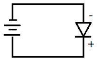
Understand diode forward bias and reverse bias
Understand diode rating
This post only focus on normal diode rating, table at below is specification for diode 1N400x series.
Important parameter for diode
Breakdown Voltage (Vr, Vrrm, Vrwm) - the diode can withstand maximum voltage in reverse mode. If reverse voltage is higher than rating value, the diode may damage.
RMS Reverse Voltage (Vr(rms)) - the diode maximum DC reverse voltage. (continues reverse voltage)
Forward Voltage (Vf, Vfm) - the voltage drop across diode in forward mode. The voltage can measure by multimeter.
Non repetitive peak forward surge current (Ifsm) - maximum forward pulse current (Surge Current).
Forward Current (If, Ifm) - the diode maximum DC forward current. (continues forward current).
Peak Reverse Current (Irm) -the diode maximum leakage current in reverse mode. when diode in reverse mode, there may have some leakage current from cathode to anode.
Example:-
For datasheet, we know that, 1N400x series diode forward current is 1A. Formula at below use to find the lowest R that can support by circuit:-
Voltage divider Formula
Vin = Vfm + (Ifm x R)
52V = 1V + (1A x R)
R = (52V - 1V) / 1A
= 51 ohm.
The R value cannot lower than 51ohm, if R lower than 51ohm, the diode may damage.
LED (Light Emitting Diode)
Example:-
Choose resistor for LED.
Base on the circuit on top, the capacitor and series of resistor are connect parallel with LED.We can ignore the capacitor path and series of resistor path, because parallel connection will have same voltage level.
Just assume, the input voltage is 5V, diode forward voltage = 2.2V Find the suitable R value.
| Rule of thumb
The LED forward current is around 5mA to 10mA. The forward current is parameter that control LED brightness. |
Voltage divider Formula
Vinput = Vled + (If x R)
5V = 2.2V + (5mA x R)
R = (5V - 2.2V) / 5mA
R = 560 ohm
Find R power:-
P = VI
= I²R
= (5mA)² x 560
= 0.014W
can use any resistor more then 0.014W.
Diode Zener
The diode zener package it look like normal diode. It forward voltage is around 0.7V (it close to normal diode), but it have difference reverse voltage value compare to normal diode.
Diode zener reverse voltage is low compare to normal diode.
Example 1
Input voltage =10V
diode zener voltage = 5.1V
Vref current = 10mA (target)
Find the R value, R power, diode zener power
1. The diode zener can regulate the voltage only, the current is control by R.
Just assume current flow throw diode zener is 1mA and 10mA through Vref path.
Total 11mA will flow throw R.
Voltage divider Formula
Vinput = Vzener + ((Iref + Iz) x R)
10V = 5.1V + ((1mA + 10mA) x R)
R = (10V - 5.1V) / (11mA)
= 445 ohm
≈ 430 ohm
2. R power
Find current across R
Voltage divider Formula
Vinput = Vzener + ((Ir) x R)
10V = 5.1V + (Ir x 430)
Ir = (10V - 5.1V) /430 ohm
= 11.4mA
P = Ir² x R
= (11.4mA)² x 430 ohm
= 0.056W
3. Just assume, Vref open circuit. all current will flow across the diode zener.
The diode zener power will be:-
P = VI
= 5.1V x 11.4mA
= 0.05814 W (min)
4. The Vref = diode zener votlage = 5.1V
Example 2
Find the Vref voltage. if input voltage is 11V.
1. The Vref = Vinput - Vzener
= 11V - 5.1V
= 5.9V
2. Power for diode zener
Itotal = Iz = Ir + Iref
Pz = Iz x Vz
Saturday, November 3, 2012
Understand Transformer - Basic
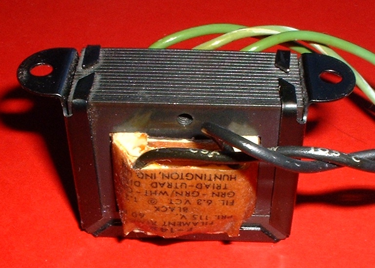
photo take from wikipedia.
Transformer
Transformer is an electric device used to transfer electric energy from one circuit to another through inductively coupled conductors. The transformer basic application is step up / step down AC Voltage. Normally, the power transformer is design at operation frequency 50Hz until 60Hz.
3 basic parameter you will found on transformer. There are primary voltage, secondary voltage and VA rating. The primary voltage and secondary voltage is indicate the transformer is step up / step down transformer.
We may found some different size transformer but have same voltage rating. what difference between those transformer? Please take note its VA parameter is difference. What is VA parameter?
The VA is maximum power of transformer. because of transformer is an inductive device. When AC signal meet with inductance and capacitance may result in periodic reversals of the direction of energy flow.
The power will transform into real power (measure in watt) and reactive power (measure in VAr [Volt-Amp-Reactive]). As what we know, the real power and reactive power may change depend transformer's load type. In inductive circuit, the capacitor may help on improve the real power.
| Note The real power is energy will drop on load and reactive power is energy will returns to the source in each cycle (AC). |
The VA is total "apparent power" supplied. This is to prevent over loading a transformer. Relationship between VA, Watts and VAr:-
VA² = W² + VAr²
Example:-
The transformer rating as below:-
Primary voltage = 230V
Secondary voltage = 15V
VA rating = 3A/50VA
1. Input voltage at primary is 240Vac, how much output voltage and max current?
a. Secondary voltage = (Vin/Vpri) x Vsec
= (240V/230V) x 15V
= 15.65V
b. Secondary current = VA / Vout
(max) = 50VA / 15.65V
= 3.19A
≈ 3A (limit by current rating)
2. How much input current, when maximum output current?
a. Primary current = VA / Vin
= 50VA / 240V
≈ 0.208A
3. If input voltage at secondary voltage is 12Vac, how much output voltage?
a. Primary voltage = (Vin/Vsec) x Vpri
= (12V/15V) x 230V
= 184V
Wednesday, October 31, 2012
Simple Adjustable Linear Power Supply dual channel
This power supply circuit is dual channel power supply. One channel is supply positive voltage and the other channel is supply negative voltage. It supply from voltage 0V to +/-15V. Maximum output current is around 1A (recommended). It limit by LM317 and LM337 voltage regulator.
This circuit is simple voltage regulator, where have not current limiting (output protection circuit). but, it is useful for who plan start the DIY electronic project or experiment.
This power supply using LM317 and LM337 is most simple power supply.
The board have some jumper, because I try to make the board small and quick.
The power supply schematic.
The input power transformer 230V to 15-0-15 (30VA)
You can download the layout.
Circuit BOM
Circuit Explanation
Transformer
This is simple circuit, but, it still have a lot of basic knowledge inside. (for electronic newbie)
First, you have to understood how to choose transformer for you circuit. you can read post at below.
Understand transformer - basic
Reservoir Capacitor (filtering capacitor)
Link here
This circuit is simple voltage regulator, where have not current limiting (output protection circuit). but, it is useful for who plan start the DIY electronic project or experiment.
This power supply using LM317 and LM337 is most simple power supply.
The board have some jumper, because I try to make the board small and quick.
The power supply schematic.
The input power transformer 230V to 15-0-15 (30VA)
You can download the layout.
Circuit BOM
| Component | Quantity | Reference Designator |
|---|---|---|
| Transformer 30VA(min) output 15-0-15 |
1 | |
| Diode 1N4007 | 8 | D1, D2, D3, D4, D5, D6, D7, D8 |
| LED | 2 | LED1, LED2 |
| LM317 | 1 | U1 |
| LM337 | 1 | U2 |
| Electrolytic capacitor 2200uf 50V | 2 | C1, C2 |
| Electrolytic capacitor 10uf 16V | 2 | C5, C6 |
| Electrolytic capacitor 1uf 16V | 2 | C7, C9 |
| Resistor 1/4W 220R | 2 | R3, R5 |
| Resistor 1/4W 150R | 2 (will difference) | R11, R12 |
| Resistor 1/4W 4.7k | 2 (will difference) | R1, R2 |
| Variable Resistor 2.5k | 2 | R4, R6 |
| Variable Resistor 100R | 2 (optional) | R4', R6' |
| Jumper | 2 (will difference) | D11, D12 |
| Reserve | 4 | C3, C4, C8, C10 |
| Terminal Block |
Circuit Explanation
Transformer
This is simple circuit, but, it still have a lot of basic knowledge inside. (for electronic newbie)
First, you have to understood how to choose transformer for you circuit. you can read post at below.
Understand transformer - basic
Reservoir Capacitor (filtering capacitor)
Link here
Subscribe to:
Posts (Atom)


